Charlie and I had a conversation at the beginning of the week about if the LiDAR module we are using is the “right” one for our purposes. The bottom line is that we don’t exactly know and so I set out to answer that question.
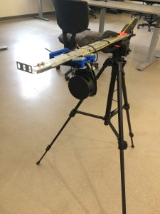
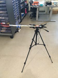
I built a controlled slider that gives us nearly 20cm of movement that we have control over when taking LiDAR measurements. My first test was to place a pencil on the ground and take 1minute of scans at each centimetre. The hope was to be able to pick out the pencil given “perfect” circumstances. After collecting the scan data, which consisted of only the distance in mm and the theta (degree angle at which the scan was take), I then artificially created a Y value corresponding to the 20cm of data taken.
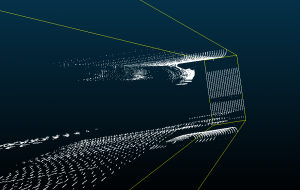
After I got the data into a pleasing form I began to try and visualise it. This proved to be a tad bit difficult and I still don’t have it quite right yet but I was able to see something;
I am fairly certain that the object towards the top of that screenshot is one of the legs on the tripod that the beam picked up. I am not entirely sure though and will continue to do tests until something is conclusive.


Leave a Reply
You must be logged in to post a comment.